The Railway - Build your own railway
Tips for the do-it-yourself railway builder.1Tools
- To cut rails and other profiles you need a cutting disc, 180 mm diameter is the most suitable.
- A good electric welding machine is a must as rail sections are welded.
- A handheld drilling machine and preferably a pillar mounted drilling machine for drills up to 12 mm is required.
- A ruler a pencil and a couple of clamps, then you have the most important tools.
2 Build straight track
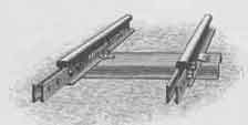
My method is to weld frames of rails and sleepers. Usually the rails are 5 meters long and weighs 4-7 kg/meter. If heavier rails are used, my method is no longer suitable due to weight and stiffness.
My rails comes from closed peat bog railways. Usually I got the rails for free. There are still rails to be found for the will be railroader.
For a 5 meter frame I usually use 5 sleepers. They can be either from cut rail profiles (80-100 cm long pieces) or the specially made sheet metal sleepers that can be found on the peat bogs.
While I manufacture straight frames in large numbers, I have made a jig from wooden planks. I fix two straight rails up-side-down against fixed stops spaced at 600 mm distance with wedges.
A sleeper is placed approximately 20 cm from each rail end, the remaining three are placed at equal distances in between. With a clamp the rail and sleeper are pressed together and welded.

3 Build curved track
On "big" railways special rail bending tools are used. If one doesn't have such a tool available another method has to be used........
When I'm making a curved track frame I have a rough idea of how sharp the bend shall be. I look up two trees standing approximately 40 cm apart. Stick the end of the rail between the trees, grip the other end of the rail and bend cautiously. Feed another 20 cm and bend again. Repeat until the rail looks as expected. I normally start with the outer rail but it really doesn't matter. A tip to simplify the track building is to leave a short stretch of straight rail at both ends.
When the first rail is bent it shall be tried at the right site to see if it has the right curvature. If adjustment is neccessary it is always easier to straighten the rail than to bend it more. When the curvature is correct the welding begins.
Start by welding the sleepers to the outer rail. One sleeper 20 cm from each end, the other equally spaced in between. Now the most tricky part of the operation begins, to bend the inner rail using a sure eye to the same radius as the outer rail ! After a couple of years training I am pretty good at it now. Bend, test, bend, test and so on. When you are satisfied the inner rail shall be welded. Make sure the rail ends are at right angle to the tangent. Distance between rail heads shall be 600 mm at rail ends, in the curved part of the track the gauge can be increased by 5-10 mm. Fix the rail to the sleeper with a clamp. Adjust the gauge at the second sleeper and clamp. Weld the first sleeper. Adjust at the third sleeper and weld at the second. Continue until ready. If you had a good eye and did not have to adjust to much during the welding, you now have a curved rail with the right radius. If not you have a problem !
As the inner rail is too long, it has to be cut and holes for the joints need to be drilled. Your first curved track section is ready.
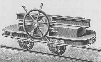
Vagn med rälsbockningsmaskin.
4 Build a stub switch
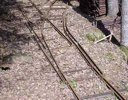
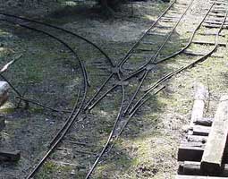
A stub switch is a lot easier to build than a point switch. The difference between the two types is shown in the picturebelow.
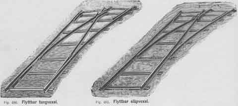
On the switch to the left, points are used to change the direction of the path. The two outer rails run continuously the full length of the switch. At the crossing the wheel is running on rails through the so called frog.
On the switch to the right, stubs are used to change the direction of the path. Points and stubs are hinged from different directions. In a stub switch no rail runs the full length of the switch. Therefore some kind of stuctural reinforcement is required. The method I have chosen is described below. At the crossing the solution can be the same as in the other switch, but as I run a few wagons with double flanged wheels, aother solution has to be used. Therefor the wheels has to run on their flanges on a steel plate through the crossing
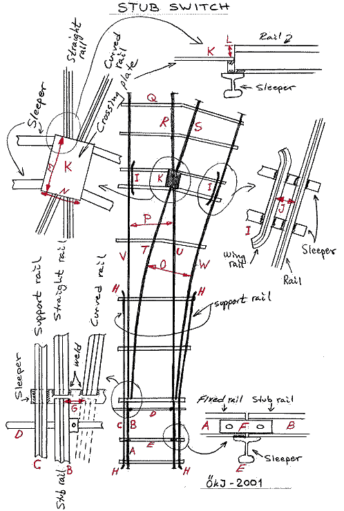
Explanation to the stub switch drawing below.
The length of the switch is 5.0 meters in both the straight and curved track.
A. 430 mm long rails welded to a sleeper at both ends. Holes for joints at both ends.
B. Movable rail, 400 mm long. Connected via a joint to A. At the free end the rail slides on top of the sleeper, pulled by the drawbar D. B should be able to move 50 mm from side to side. This is also the distance between the rail heads of the straight and curved rails (G). Those rails are welded to the sleeper.
C. Structural rail, one on each side of the switch. Those rails are required because otherwise the switch would not hang together. Length approximately 2 meters.
D. Drawbar, used to move the stubs between the straight and curved tracks. Conneceted to both stub rails by bolts.
E. As sleepers I use rails cut to suitable pieces. Rail A is welded to the sleeper. Rail B is connected to A with the joint F. Use loosely fitted bolts.
F. Rail joint.
G. Distance between rail heads shall be 50 mm to allow wheel flanges to pass freely.
H. The ends of the structural rails shall be bent outwards. This will allow the use of double flanged wheel sets.
I. Wing rails are used opposite of the crossing to prevent derailing. These are approximately 60 cm long and has bent rail ends.
J. Distance between rail heads is 30 mm for the type of wheels I use. They have a flange thickness less than 30 mm.
K. The crossing is made up by a steel plate with the top surface 25 mm below the adjacent rail head.
L. This measure is depending on the measures of the flanges used. My wheels have 25 mm high flanges.
M and N. The size of the steel crossing plate is approximately 300 x 200 mm.
O. The gauge in the curve should be a little larger than the nominal gauge. 605-610 mm is suitable.
P. Gauge here is 600 mm, but 595-605 mm is ok.
Q. The sleeper rails are bent at their centers so they can be welded to the track rails at right angle.
R, S, T and U. These rail lenghts has to be tried out on a case by case basis. The length depends on the curvature of the curved rail. Normally R and S are 500 mm long.
V and W. As the total length of the switch is 5000 mm, V and W shall be 4150 mm long each.
